Example of expanding an existing network by connecting an additional Keenetic router
Let's assume that a router is installed at a facility, through which the local network accesses the Internet via an Ethernet cable. Using an additional Keenetic router, you need to expand the existing network and organize access by connecting clients via Ethernet cable and Wi-Fi, as well as create a guest Wi-Fi network.
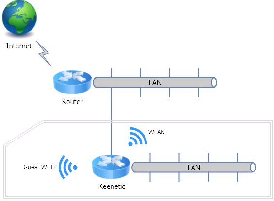
This example considers a 'non-standard' scheme and operating mode for a case where there is already an existing network with Internet access. For example, this could be a corporate local network ('enterprise network'). The Keenetic router will act as a regular access point for the main network, and a guest network will be set up on it, with IP addresses assigned by this Keenetic router itself, and packets from the guest network forwarded to the higher-level network via NAT.
We will use Keenetic Hopper (KN-3811) as the additional router. The network to which it needs to be connected has its own gateway with the address 192.168.101.1 (which also serves as the DNS and DHCP server) and a network mask of 192.168.101/24. We will leave one switch port working in the preconfigured Home segment, while the other ports will be used in the enterprise network. In addition, the device will provide a wireless connection within the enterprise network, as well as a guest network (isolated from the enterprise network).
1. Connect a computer to the grey port of the local network and the company network to the blue port of the device. Reset the settings to factory defaults. Next, after rebooting, go to the device's web interface at 192.168.1.1 (during the process, you will need to decline the Initial Setup Wizard, confirm your agreement to the terms of use, and enter a password for the administrator account). According to our diagram, the device should already have Internet access with this connection. If the company network is also 192.168.1/24, like the default Home segment in the router, then at this step, you should change the address of the device's home segment to one that is different from the company network by mask, for example, to 192.168.2.1. You will then need to reconnect to the web interface at the new address.
2. In the web interface, on the System Dashboard page, identify the port to which the computer is connected.
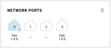
In our example, this is port number 3.
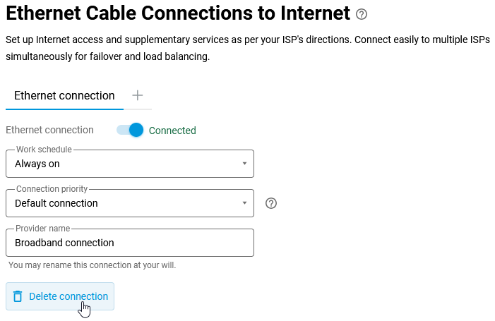
On the Ethernet Cable page, delete the Internet connection (in our example, this is Ethernet connection).
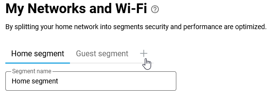
Go to the My networks and Wi-Fi page and add a new segment to the device's local network.
In the settings for the new segment, you will need to specify the use of ports other than the one to which the computer is currently connected.
In the IP Settings section, specify a unique IP address in the enterprise network that will not be assigned to another device, disable the DHCP server in this segment (since the enterprise network already has its own server), and uncheck Use NAT.
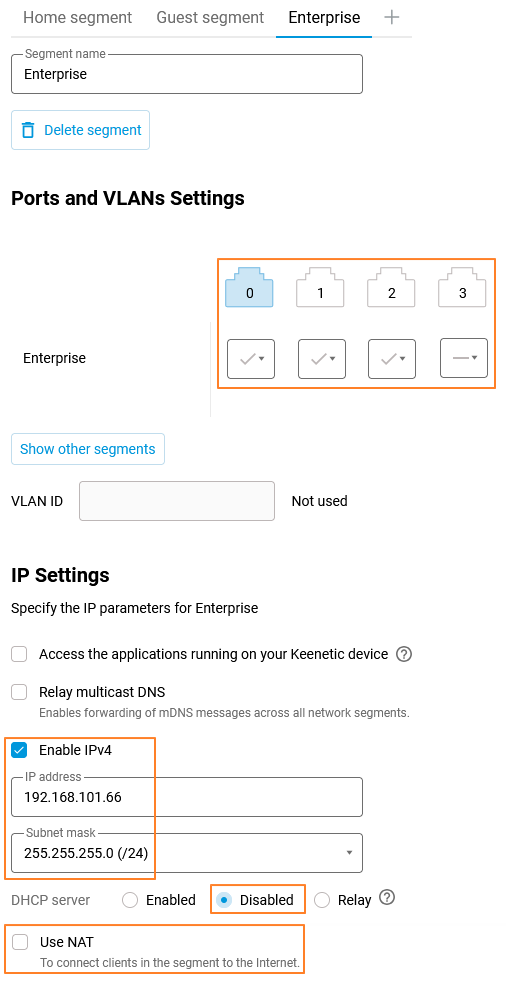
At this stage, you should also enable the wireless network for this segment and configure the connection parameters as required. This is because in the next step, we will execute commands that will hide the settings for this segment from the web interface.

Save the settings.
3. Further actions must be performed using commands. The router's command-line interface (CLI) also works through the web interface (Web CLI).
Run the show running command to display the current router configuration:
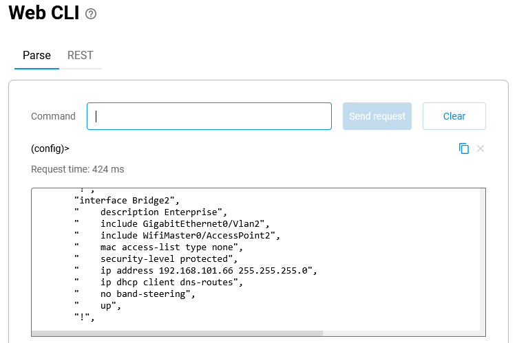
In our example, the segment added in the previous step was assigned the interface ID Bridge2. To enable the router to access the Internet through it, execute the following commands in sequence:
interface Bridge2 security-level public
interface Bridge2 ip global 65534
ip route default 192.168.101.1 Bridge2
ip name-server 192.168.101.1 "" on Bridge2
system configuration save
If you want the router also to obtain an IP address, gateway address, and DNS settings from the DHCP server, then you do not need to execute the commands:
ip route default 192.168.101.1 Bridge2
ip name-server 192.168.101.1 "" on Bridge2
The bridge configuration should look like this:
interface Bridge2 security-level public
interface Bridge2 ip global 65534
interface Bridge2 ip address dhcp
system configuration save
4. On the System Dashboard page, the Internet panel now displays the following information:
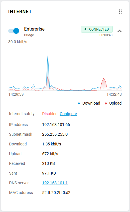
The following steps remain to be completed:
A. Disable the access point in the preconfigured Home segment (this can be done directly on the System Dashboard page).
B. Enable and set up Guest Wi-Fi (on the Guest segment page). You can also add a network port to the Guest network segment on the device and connect another access point through it.
C. Make sure that on the Domain Name page, the Cloud access is enabled on the KeenDNS tab, and the Allow access from the Internet option is enabled for remote device management.
Note
1. Settings made via the command line may be reflected in the web interface in unexpected ways. Additionally, when saving changes to the device configuration, there is a possibility of disrupting the working settings. Therefore, we recommend that, after verifying that the scheme is functioning as required, you save a backup copy of the startup.config.txt configuration file.
2. To display the Bridge2 segment settings in the web interface again, enter the command interface Bridge2 security-level private. Internet access from the Home and Guest networks will no longer work in the system configured as described above. To restore it and hide the Bridge2 segment from the web interface again, specify interface Bridge2 security-level public.
3. This connection scenario, provided that you do not need to connect directly to the corporate network via Wi-Fi through the device, can be easily configured by simply switching several ports to TV set-top box mode (on the Ethernet Cable page in the Ports and VLANs section). The guest network will also work, as will the wireless access point in the Home Network segment.
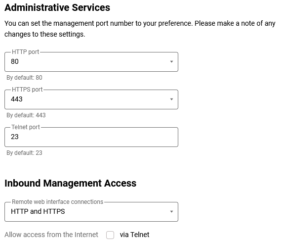
4. To access the router's web interface via its IP address, you need to set the value to HTTP and HTTPS in the Inbound Management Access field on the Users and Access page, Remote web interface connections section: