Configuring IPIP, GRE, and EoIP tunnels
General Information
IPIP (IP in IP) is one of the easiest tunnels to configure. This protocol encapsulates only unicast IPv4 traffic.
GRE (Generic Routing Encapsulation) allows for the encapsulation of virtually any type of network protocol and supports broadcast traffic. GRE tunnels are compatible with hardware security gateways, Mikrotik routers, Linux routers, and other equipment that supports GRE (e.g., Cisco and Juniper).
IPIP and GRE tunnels are network-layer (L3) tunnels in the OSI model, created when IP addresses are available at both ends. Routing (including default routes) can be configured through them in the same way as through any other interfaces.
An EoIP (Ethernet over IP) tunnel is a data link layer (L2) tunnel in the OSI model, operating on top of the network layer (L3). Data is transmitted through an EoIP tunnel at the Ethernet frame level. EoIP allows you to create a transparent network environment that emulates a direct Ethernet connection between networks. All MAC addresses remain visible, and this type of tunnel can connect two local networks at the data link layer (L2) over the Internet. EoIP uses GRE as its transport protocol. An EoIP tunnel can operate over IPIP, WireGuard, and any other connections capable of transmitting IP packets. In addition to IP traffic, it can carry other traffic types, including ARP, DHCP, PPPoE, IPv6, and others. By default, ARP-based subnet scanning is enabled in the tunnel.
Important
IPIP, GRE, and EoIP tunnels are point-to-point tunnels. Both ends of the tunnel must have public IP addresses or be on the same network (there must be no NAT address translation between them).
In the basic configuration, no security measures are provided for these tunnels (no encryption or authentication mechanisms).
IPIP, GRE, and EoIP tunnels operate without maintaining connection state (they are called stateless or connectionless), meaning it is impossible to determine whether a tunnel is operational. The only option is to configure both ends and then verify data transmission.
Preparing for Configuration
To configure connections using the IPIP, GRE, and EoIP protocols, the IP-IP VPN tunnelling, GRE VPN tunnelling, and EoIP VPN tunnelling components must be installed.
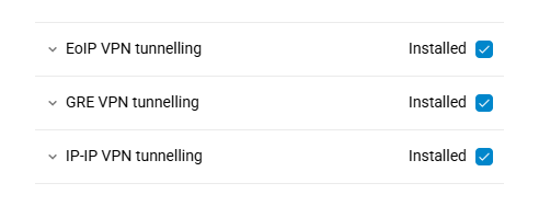
As an example of setting up IPIP, GRE, and EoIP connections, we will use Internet connection interfaces with public IP addresses on both sides of the tunnel.
Important
When setting up IPIP and GRE tunnels to connect two different subnets, the addresses of these subnets must not overlap. For example, one end of the tunnel should have the subnet 192.168.0.0/24, and the other 192.168.1.0/24.
To ensure that a subnet is correctly routed through a tunnel on the router, that subnet must not be in use on any other interface.
Example of Configuring Basic IPIP and GRE Tunnels
IPIP and GRE tunnels are configured identically. The difference is that IPIP uses IPv4, whereas GRE can use other protocols as well. Additionally, GRE, like TCP, can verify packet integrity via a checksum.
Let's look at an example of creating an IPIP tunnel for one-way access between primary segments of two routers. On the local router, the primary segment has the subnet 192.168.0.0/24; on the remote router, 192.168.1.0/24.
On your local router, go to the Internet menu section, navigate to the Other Connections page, and under IP-Encapsulated Tunnels, click Create connection.
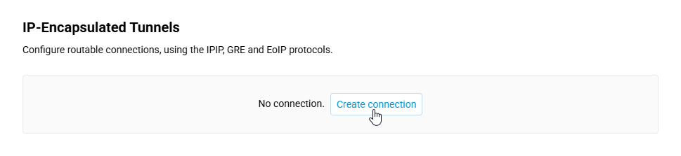
Configure the tunnel by entering an available address from the private IP address range in the IP address field. In our example, we'll use the address
192.168.255.1. In the Remote destination field, enter the address of the remote router's external interface (public IP address).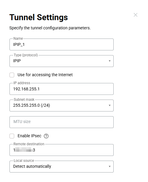
On the remote router, add and configure a tunnel by specifying an available address in the IP address field from the same private IP subnet you used on the local router, for example,
192.168.255.2. In the Remote destination field, enter the address of the local router's external interface.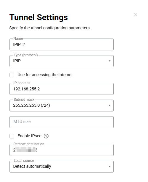
On the local router, in the Network Rules menu section, navigate to the Routing page, and add a route by clicking the Create button.
In the route, specify the subnet of the remote router's primary segment (
192.168.1.0, subnet mask255.255.255.0). In the Interface field, select the name of the tunnel you are configuring. Check the option Add automatically.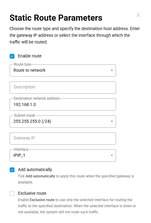
On the remote router, in the Network Rules menu section, navigate to the Firewall page, and click Add rule.
In the rule, select the Interface for the configurable tunnel, and then specify the Destination IP for the primary segment's subnet on this router (
192.168.1.0, subnet mask255.255.255.0). For simplicity, selectIPV4(formerlyIP) as the Protocol, which includes the protocols required for most tasks: TCP, UDP, and ICMP (Ping).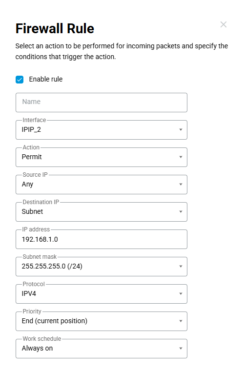
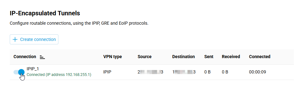
Enable the IPIP or GRE connections you created by setting the switch to the On position on both sides, and wait a moment for the connection to be established. It usually takes less than a minute.
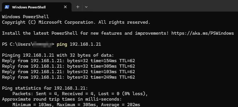
To verify that the tunnel is working, send ICMP packets (Ping) to a client on the remote router's network.
Tip
If you need bidirectional access between these segments, configure the routing and firewall settings identically on both sides.
Example of Configuring a Basic EoIP Tunnel
The primary use of EoIP is to combine subnets into a single network at the data link layer (L2).
Let's look at an example of connecting the primary segments of a network using two routers.
In this example, the IP address 192.168.0.1 is assigned to the primary segment on the local router. The primary segment of the remote router will be combined with the local router's segment.
Important
Since the networks will be combined at the data link layer (L2), the DHCP server on one of the routers in the combined segment must be disabled. Otherwise, having two active DHCP servers will result in IP address conflicts and unstable network performance.
Tip
It is recommended to disable the DHCP server and/or change the IP address in a segment when connecting to another segment on the same router or remotely via KeenDNS.
Disabling the DHCP server in the segment to which the device is connected will result in the loss of access to the router's web interface on that segment.
To restore access when the DHCP server is disabled, you must manually set a free IP address from the same subnet in the device's network settings.
On one of the routers, set a free IP address from the subnet of the other router you are connecting to, and disable the DHCP server. In this example, the IP address
192.168.0.2is set, and the DHCP server is disabled on the remote router. You can change the IP address and disable the DHCP server in the My Networks and Wi-Fi menu section on the Segments page within the settings for a specific segment.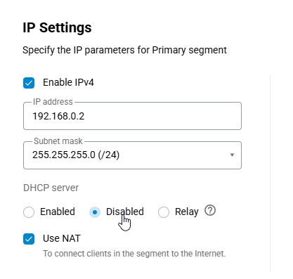
On the local router, go to the Internet menu section, navigate to the Other Connections page, and under IP-Encapsulated Tunnels, click Create connection.
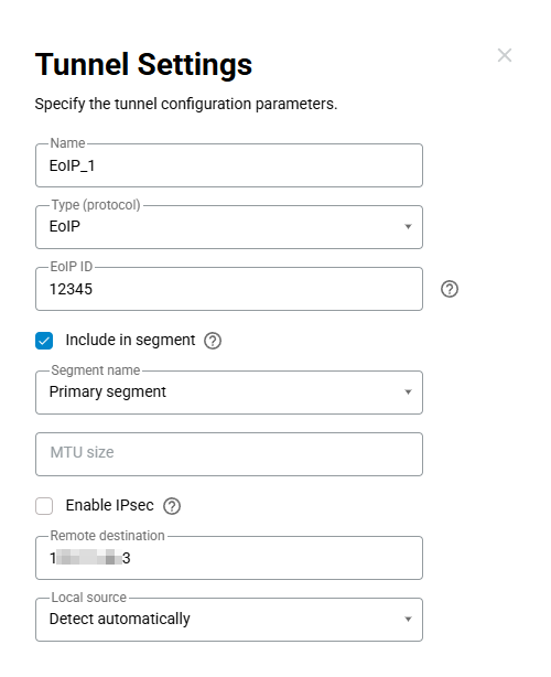
Select the EoIP protocol. In the EoIP ID field, you'll need to enter the same value on both sides of the tunnel. Check the Include in segment option and select Primary segment below. In the Remote destination field, enter the external interface address (public IP address) of the remote router.
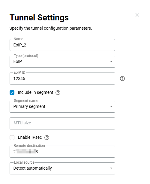
On the remote router, configure a similar tunnel, but in the Remote destination field, enter the address of the local router's external interface.
Enable the EoIP connections you created by setting the switch to the On position on both routers.
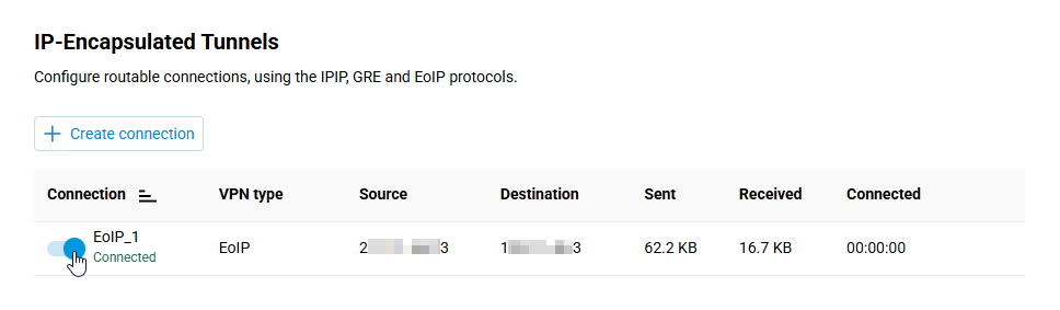
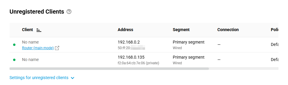
If the connection was established successfully, the devices connected to the remote router's primary segment will appear in the My Networks and Wi-Fi menu section on the Client Lists page.
Adding IPsec Encryption
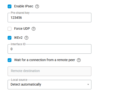
On the Other Connections page, under the IP-Encapsulated Tunnels, click the required IPIP, GRE, or EoIP tunnel, and in the tunnel settings, check the Enable IPsec option. This option must be enabled on both ends of the tunnel.
Note
When IPsec is enabled, the tunnel's MTU size should decrease. If it were set manually, you would need to adjust it.
The value in the Pre-shared key field must match on both sides.
The Force UDP option may be necessary if one of the parties is behind a NAT with port forwarding configured on that side. If you need to use this option, it must be enabled on both sides of the tunnel.
Enable IKEv2. The value in the Interface ID field must be the same on both sides.
To ensure the tunnel functions properly, enable the Wait for a connection from a remote peer option on one side. When IPsec is enabled, only one side should initiate the connection.
Notice
Tunnels based on EoIP/IPSec and GRE/IPSec are incompatible with PPTP connections because they use the same GRE protocol. In this case, there is only one available option: IPIP/IPSec.